
Getting Started
I was finally able to start construction of the observatory in mid-2023. I was mostly working alone, but for some jobs that I just couldn’t complete myself, I had to enlist help, such as a hiring a backhoe for trenching. I decided to build a round building under the dome, as I already had a 14’x30′ metal building on site that I could use as a “warm room” and office. Once AC power and CAT-5 are run, the two buildings will be connected together via my network.

Trenching to install a conduit for power and the network cable, and also digging a hole for the pier, was done in conjunction with running a water line from our well out in the field to my new garage and garden area. The ground here is a thin layer of soil over increasingly thicker layers of underlying shale rock. The layers started out so thin a shovel could break them up, but steadily became thicker to the point that the small backhoe doing the job could not dig much deeper.

After shoveling out loose soil and rock from the hole for the pier, it is about two and a half feet deep. The bottom is a thick bed of shale. A reinforced concrete pad will be poured on top of it before building a concrete block pier base.
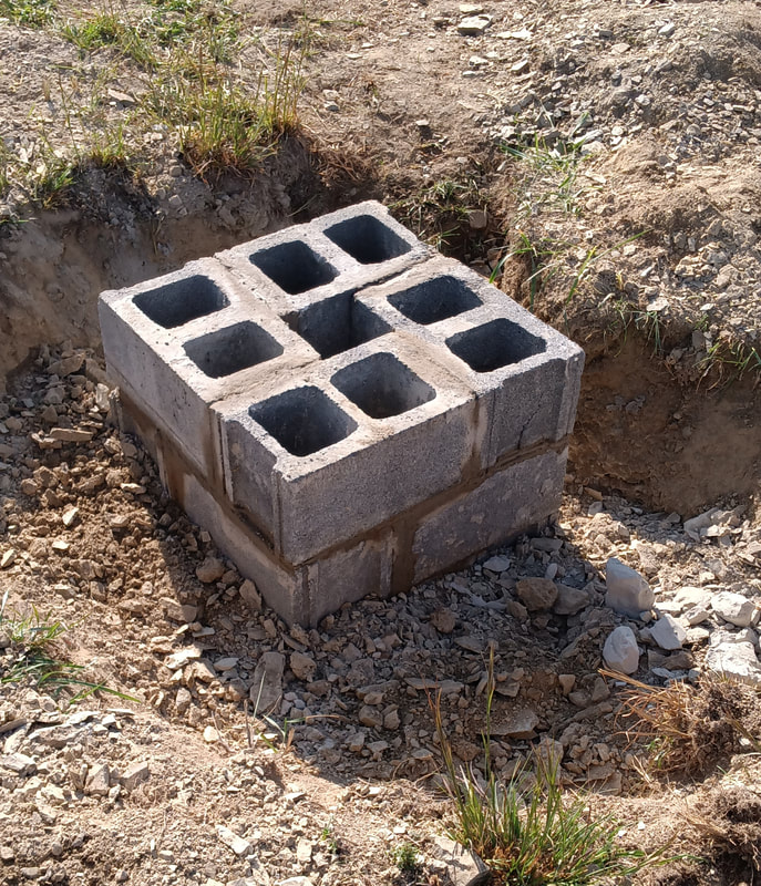
The block base is three rows high in the photo, and sitting on the concrete pad. Shale and dirt are already being packed back in around it. Two more rows will be added as the observatory foundation progresses, and in the end the base will be about 4 feet tall, although a good portion of it will be underground. It will be filled to the top with concrete once finished.
Building the Foundation

Digging by hand in preparation for pouring a footer for the foundation. It will be about two feet deep, enough to ensure the footer is below the frost line. Another row of block has also been added to raise the pier base high enough not to get dirt in it. All this digging was done by hand because there was no budget for a backhoe just for this one job.

After multiple days of digging and shoveling, cut up pieces of cattle panels were laid down as rebar before pouring the footer. It took twenty-six 80-lb bags of ready mix concrete, weighing over 2080-lbs. No wonder my back aches.
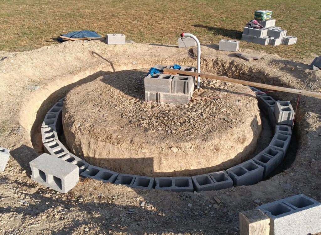
The first row of blocks is done and just starting on the second row. Two rows will bring the foundation up to about ground level. The outer diameter is 12′ 2″ and uses exactly 26 blocks for a full circle. I’ve never actually laid blocks before, but I’ve watched others do it since I was a kid, so I do know what needs done, more or less. I don’t have the budget to pay a brick layer to do the work, and it would be extremely difficult to find one on short notice anyway.

There are four rows total, and for the top two rows that are visible, I switched to split-face blocks that match the house foundation. Actually they are leftovers from the house foundation, except I came up five short, and had to make a three hour trip to the block company for more. Because of the doorway, there’s only twenty-four blocks per row for the top two rows.
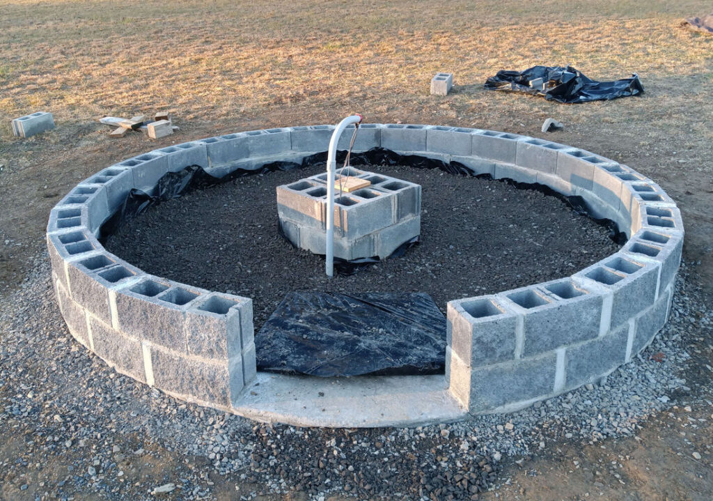
I worked all day on a Saturday to finish mortaring all the joints. This was late Fall 2023 and the weather was alternating between cold, rainy days and the occasional nice day, so I worked every good day that came along. I’ve also cleaned up all the excess dirt from digging the foundation, both outside and inside. Then I laid down a vapor barrier inside and poured crusher run on top, thinking this would be good enough, and save the cost of pouring a concrete floor (Note from the future: not pouring concrete inside while it was easy comes back to haunt me later).
Constructing the Building
It’s late, late Fall of 2023 and I was hoping to get the floor done before it got too cold to work. The sill plate and outer band are made from individual block-length pieces joined together with metal plates and J-bolted to the foundation. The joists are 2′ X 8″ lumber and the sub-floor is AdvanTech sheeting. This as far as I progressed before the snow came, so everything ended up tarped over until Spring.
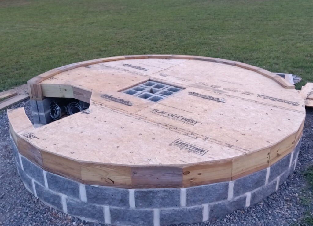
It’s Spring 2024 and the floor is finally done. The wall plate is in the process of being put down, and one final row of block has been added to the pier base, bringing it up to its final height. The open cutout in the floor is for steps.
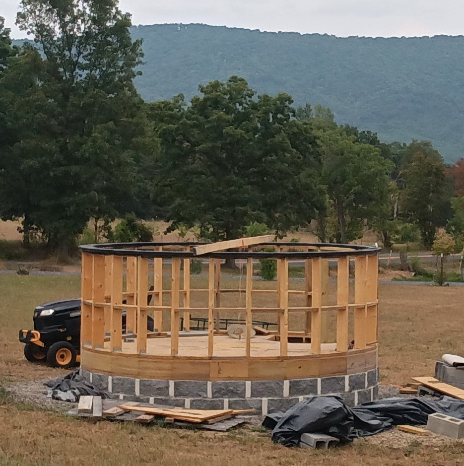
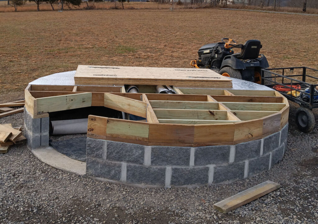
The walls have been studded up. The Ash dome manual I’m using shows Ash supplied dome base ring that went on the top of the wall for mounting the azimuth wheels, but I didn’t get a ring with this Lancaster dome, so I had to make one. It’s cut from 3/4″ plywood in 4-foot sections. It is actually two rings stacked and glued together to make a single ring 12′-2″ in diameter and 1-1/2″ thick. In the photo the ring is painted black to seal it up in case of rain.
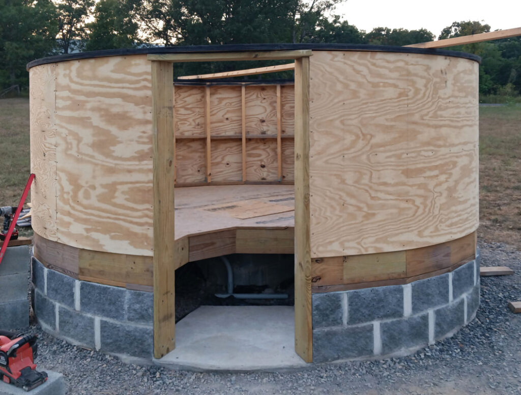
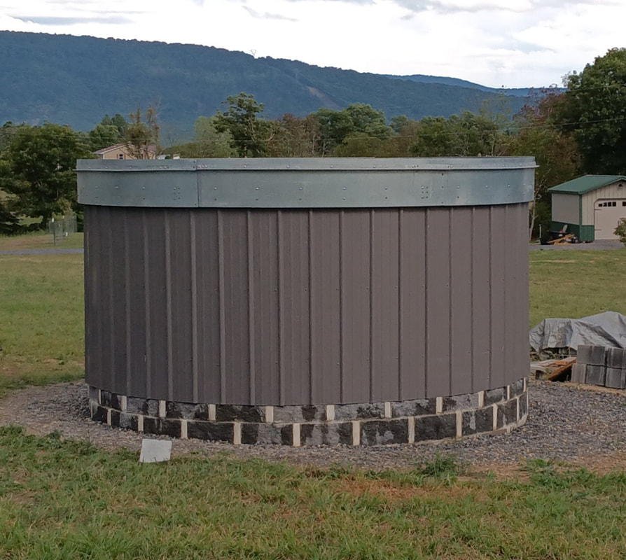
After making sure the building was as round as possible, 1/4″ exterior grade plywood was installed. Also, a concrete pad was poured in the entry way and then the door was framed with pressure treated lumber. The ring on top was installed according to the Ash manual, being leveled with shims and bolted to the top of the wall with 1/2″ carriage bolts.
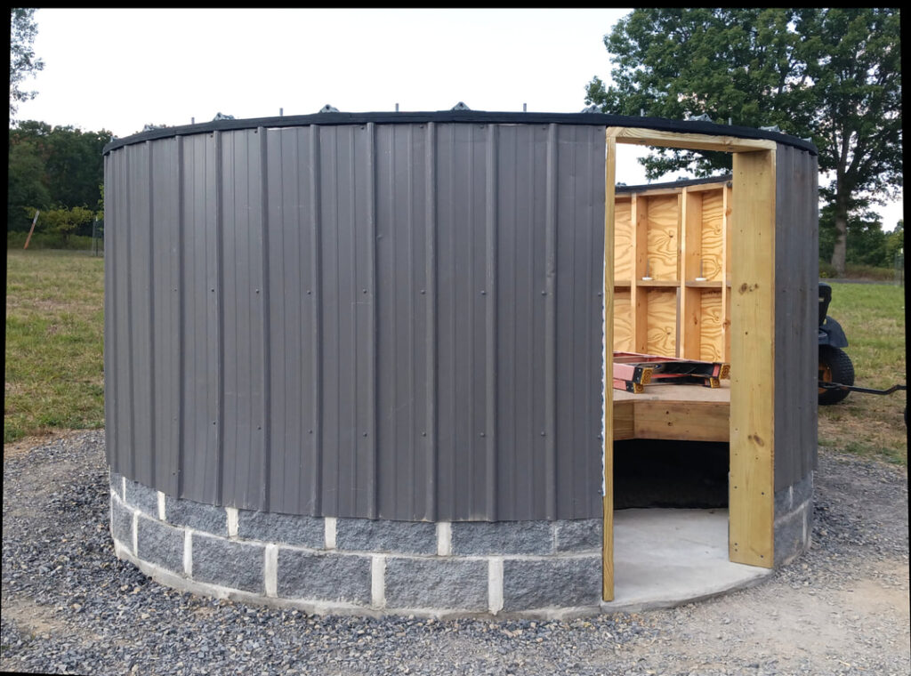
The metal siding is leftover pieces from the roof of the log home we built some years back, and sold before moving here. It got kicked around for about five years, so it has its share of scratches, but using it saved me money.
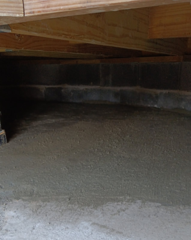
The plastic vapor barrier covered with gravel has now come back to haunt me. It was a very hot summer, with temps hitting a hundred on a regular basis, and my Australian Shepard liked to lay under the floor on those hot days, while I was sweating away up above. Unbeknownst to me, he dug up the gravel, and the plastic barrier, in multiple spots while making himself comfortable. So I finally admitted I should have poured a concrete floor and set about fixing it. I had to rake out the gravel, trim up and repair the vapor barrier, and lay in more cut up cattle panel for rebar, before pouring a concrete floor. Not an easy task at all now that the wooden floor was installed. I also cut an access hole in the floor to make getting in there easier. I should have poured concrete from the very start, but was trying to save money.
Constructing the Dome

The dome rotates on twenty-three garage door rollers. I can’t remember now why twenty-three, but that may have just been how many mounts were in the box. The rollers I’m using are 3″ polypropylene commercial rollers with sealed bearings and stainless steel shafts. The wheel mounts are galvanized and came with the dome, but had sat in a box for probably twenty years, and were heavily oxidized. Before installing them, they were cleaned and coated with cold galvanizing compound. Also, under each mount is a 1/4″ thick neoprene rubber pad. After test fitting, the mounting holes were drilled through the base ring for 1/4″ bolts.

A lot of the dome’s hardware was missing, and what was there was mostly corroded, so I ordered all new stainless steel hardware. So far I’ve ordered over 600 screws and bolts, plus nuts and various types of washers. I’ll order more later as I need it.
The dome’s base consists of six segments. This base ring had been previously assembled and drilled for bolts, but none of the segments were marked, so I had to sort them out by matching up bolt hole patterns. Five of the six slid right onto the rollers, but for the last piece I had to remove and mount the wheel track first, then slip the segment in from above and bolt it back together. The braces, gear track, and wheel track for each segment were already installed when I bought the dome, but I replaced all the old hardware with new stainless steel.

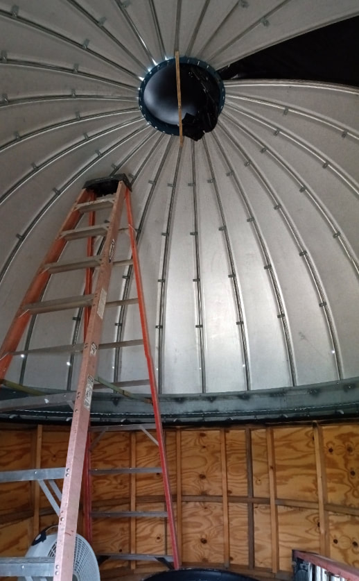
This is a day I have long awaited, actually assembling the dome panels. On the first day of panel assembly we (my wife helped) only managed to get 8 panels mounted because of the learning curve and prep work. A Lancaster dome has a steel ring in the top to tie all the panels together, and it has to be supported until a sufficient number of panels are added to make it self-supporting. That’s why all the wooden blocks are stacked on the ten-foot step ladder. The only hurry here is to get all the panels installed before any windy days come along.

We hoped to finish installing the panels on the second day, but didn’t quite get there. We’re getting faster as we go though, and at this point we have 21 out of 26 panels on.
We worked until dark and as we wrapped up for the day my wife spotted a train of Starlink satellites marching across the sky, heading eastward. They were very bright and still close together, so they must have been “released into the wild” fairly recently. I think this was on September 6th and I saw online that SpaceX had launched twenty-one Starlinks on August 31st, so I’m guessing this was them.

The third day and finally all the panels are in place. The remaining gap is where the shutter aperture will be cut out. The ring in the top will also get cut out. This dome is a lot more hands on than a pre-cut, pre-drilled kit.
A look inside reveals all the dome clips tying the panels together. These are zinc-plated and had also been oxidizing away in a box for twenty years, so they were coated with cold galvanizing compound as well. I was also short about seventeen clips, but then I discovered Virginia Silo Company was less than two hours drive away and they not only had the clips, but gave them to me without charge. Kudos to Virginia Silo.
Finishing the Interior and Pier

Finishing touches on the inside include a railing around the stair well, to prevent anyone from accidentally falling into it, not that I would know anything about that. Let’s change the subject. All the material for the railing was leftover from our front porch and rear deck projects on the house. The walls were lined with reflective bubble foil before installing Luan paneling.
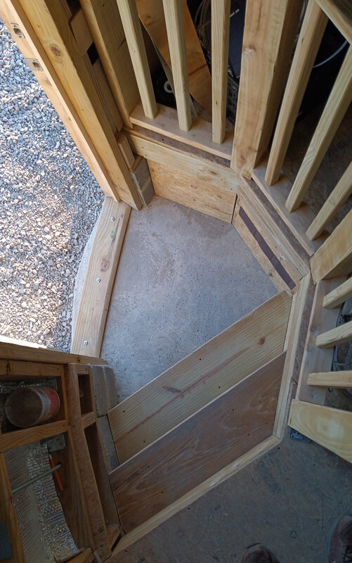
The entry and stairs have also been finished up. It’s two steps (three if you count the floor) up to the wood floor. The stairs are open underneath so no creepy crawlies have a place to hide. Panels were installed to close off the under-floor area, but a vent was added for air flow. The rails and steps will be finished with Australian Timber Oil. The door is not a standard size, it’s approximately 69″ high and 31″ wide, so one was custom made instead of trying to chop up a prefab door.

To finish the pier, the base was filled with concrete and rebar was added. I also installed a short conduit from the side of the pier under the floor up to where the metal pier bolts on top.
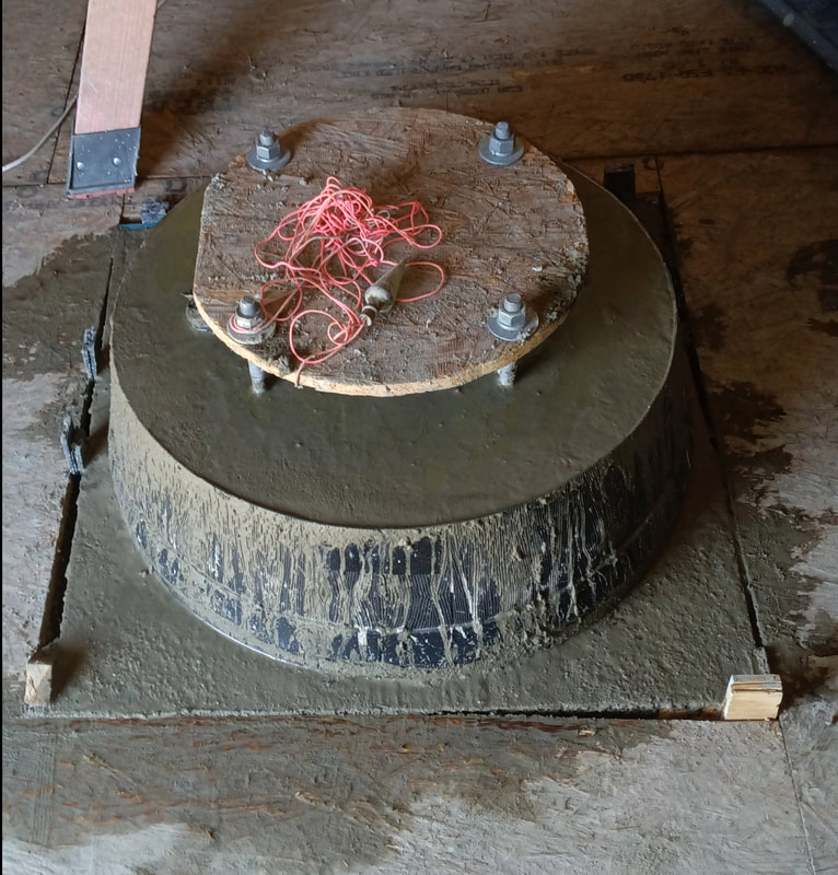
The concrete on the square pier comes up level with the subfloor and then transitions to a round base. It will be less of a trip hazard than having square corners jutting out. The round form was made from a large plastic planter from Tractor Supply. It was cut down to 7-1/2″ high, which makes the final pier height of the steel pier 60-1/2″. Galvanized J-bolts were set into the top for attaching the metal pier.
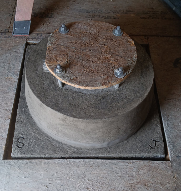
The finished base was allowed to set up for a couple of weeks before installing the heavy pier. Also, now that the forms have been removed, there is a gap between the floor and base, to prevent vibrations being transmitted into the pier. The base is also isolated from the concrete floor below, but the gap there is filled with foam to keep critters and moisture out.

I guesstimate the metal pier weighs at least 150 to 200 lbs, probably more. No way I’m picking that up by myself, so I lifted it into place with a chain winch hanging from a wooden beam supported by two ladders. The pier is adjustable from about 39 to 42 inches high, the center pipe is 10″ in diameter and is 3/8″ thick steel. The top plate and bottom plates are 1/4″ thick. The top adjustable plate and bolts are not yet installed.

Ready for paint. The pier has been set, the walls are installed, the entry way is done, and the floor sanded. Next the floor and stair rails will be sealed with timber oil. I also built a curved table out of leftovers, that fits tight against the wall, and it will also get a coat of timber oil. The open panel beside the table is where the cables from the pier come up from under the floor. That panel will go on later.
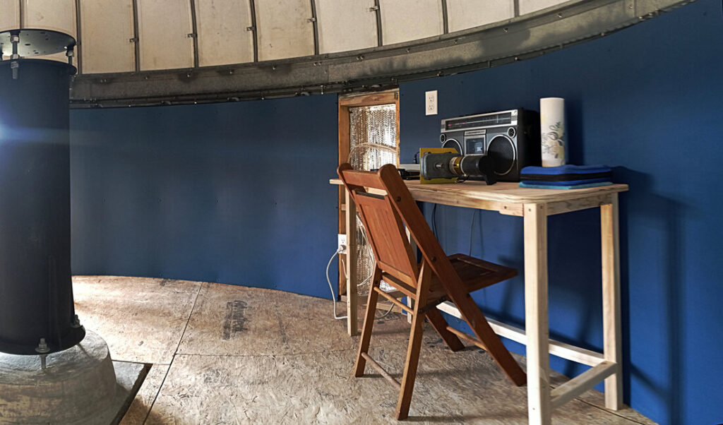
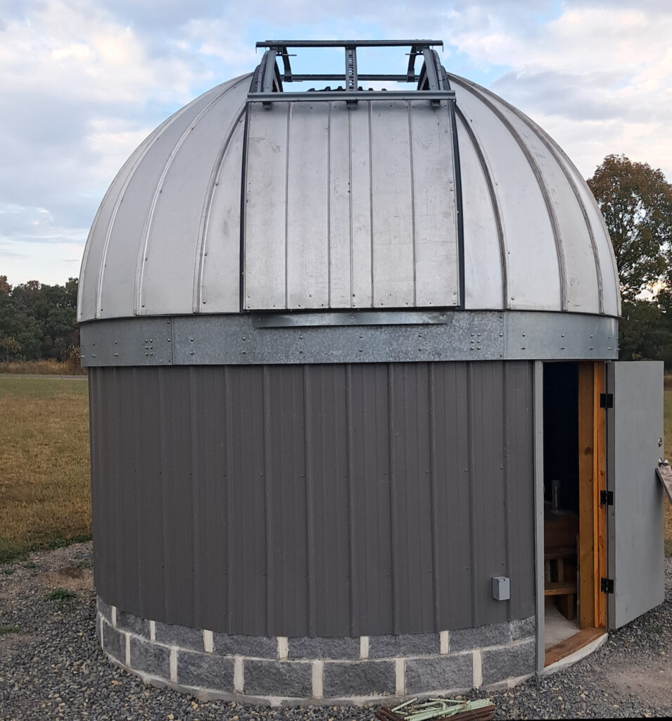
And now there’s paint. I call it star chart blue, but Benjamin Moore calls it New York something or the other, I forget. I also have a black rubber floor to put down once the dome’s shutters are finished and all the ladders are gone.
Finishing the Dome
As I was assembling the dome I discovered some parts for the shutters and shutter tracks were missing. When I originally purchased the dome I was told it was complete, but since there wasn’t a manual or a parts list, and I wasn’t familiar with it, I had to take their word for it. Turns out there are parts missing for the shutter, including the curved metal flashing that goes around the aperture, the shutter support track spacers, and the curved garage door tracks that the shutter wheels roll in. Also, there are many lesser items not included, such as rubber weather seals around the shutter, or the motor mounts or the dust seal between the wall and the dome. I worked with a couple of local metal fabrication shops to make the missing flashing, and motor mounts, but I can’t find any company that can bend garage door tracks, a problem I’ll have to solve myself.

I also noticed an issue with the dome randomly rubbing on the wheel ring as it rotates, due to play, or runout, in the wheels, and also probably the dome not being perfectly round. So, I added four horizontal “anti-runout” wheels around the wheel ring. This is also how Exploradome handled this issue and it completely eliminates the rubbing.

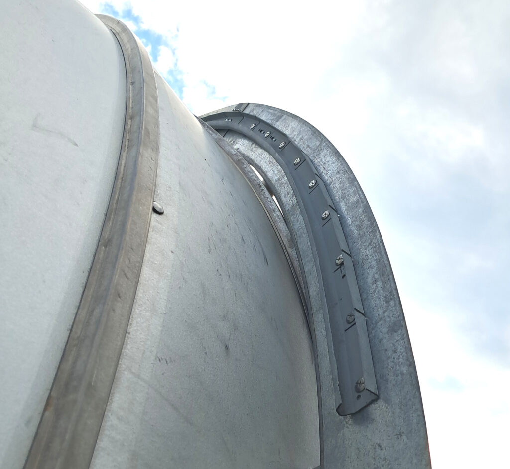
As previously mentioned, I was missing all the spacer blocks for the outer shutter track supports. The Ash manual showed ten blocks on each side. I made replacement spacers from 1-5/8″ round aluminum stock and each block is more or less unique, so measuring, cutting and installing them was a bit tedious. I also placed an 1/8″ neoprene sealing washer under each one. I ended up with nine spacers on one side and eight on the other because I can’t count, plus the ridges on my dome are of a different style than Ash’s, being a little larger and less symmetrical from side to side.

An example of the support blocks installed on the dome. It’s also shows how the ridges can get in the way of installing blocks. Because of the difference in these seams compared to the panels Ash uses, I wanted to avoid drilling holes through any of them.
To custom cut the spacer blocks I purchased a table-top, metal cutting bandsaw. Each block has one side cut on angle, and the bandsaw made cutting them a breeze. It was literally an indispensable tool for this job.

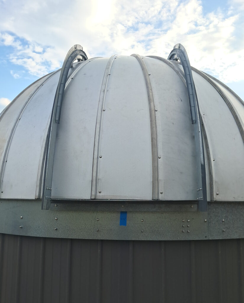
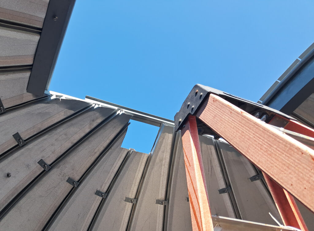
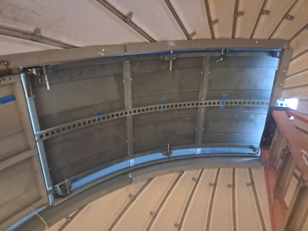
With the outer track supports finally installed, I could start cutting the opening out to its full 42″ width. In this photo the top section of the opening has not yet been cut, because my 4-1/2″ angle grinder was too small to cut through all the closely spaced ribs on top along the rails. I ordered a 6″ angle grinder for this task, but while waiting for it to arrive, I began installing the curved, right-angle flashing around the inside of the lower part of the aperture.

The last pieces of the panels have finally been cut out of the shutter opening. Now the remaining flashing can be installed, and the seams caulked.
The next big step is installing the shutter tracks, once I’ve figured out how to bend them.

I can’t just bend the wheel tracks as is without the use of custom dies that prevent the track from twisting and bulging as it bends. So, I cut the top edge and the back of the tracks at five inch intervals, down to the beginning of the curved bottom section that the wheel rolls in. This allowed me to bend it without causing much twist or deformation, as was happening with the uncut track. I have pieces of both thinner residential-grade and heavier commercial-grade tracks to work with. It is easier to bend the thin stuff, but I prefer to use the thicker grade track for the shutter.
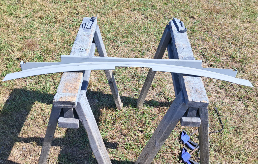
It may not be pretty, but it is curved. The small, leftover piece of outer track support shows the exact curve needed. The track’s curve is not perfect yet, and still needs some tweaking, but that can be done during the process of mounting it. But first the cuts need dressed and the whole track painted with cold galvanizing compound.
This 13-ft piece of track is one of two that came from an old, very tall garage door that was replaced at a metalworking company, and were given to me. I had to clean off decades of caked-on grease, but they are still very serviceable. They’re not quite long enough, but I have another short section that I can add onto each one. These short sections also came with the long tracks. In the end I really didn’t need the short sections, although I did install them so the track runs all the way down the back of the dome. But it worked out that the stops for the shutter wheels are actually mounted at the end of the long sections. It amazes me how I was given some old tracks that turned out to be exactly the right size. Someone is looking out for me.

The drop down door has been installed to see how things are lining up, and to mark the starting point of the tracks. It might need to come off again in order to install the shutter, but I’ll try to avoid it.

I’m finally at the point of being able to install the wheel tracks. In order to bend each five-inch section to form the proper curve, I have to anchor the track with a bolt at each cut so I can torque the next 5-inch section into perfect alignment. It’s a lot of screws, and holes to drill, but it works, and I now have the shutter tracks that I had little idea of how to make just a few short months ago. And the end result looks pretty good.
Both thirteen-foot sections of track are mounted. Before the two small sections are added to the ends, I want to try sliding the shutter into place, then I won’t have to remove the drop down door again.
Here is a closeup view of how the track is mounted. Overall, this has worked out really well, and I don’t know how else I could have been done it since I don’t have the proper tools and dies. This is the back side of the shutter track supports, which for reasons unknown to me, are 2-inches wider than the front sections. That’s why the wheel track is not mounted flush to the edge here.
The shutter is fairly heavy and bulky and I can’t move and mount it by myself. A friend has been helping me recently and he dismantled the shutter so it could be cleaned, coated inside with cold galvanizing spray, and have some damage to the skin repaired. The individual pieces are much easier to handle which gave me the idea of mounting the shutter one piece at a time, and reassembling it in situ. So, before installing the small sections of track on the rear, me and my wife rolled the shutter’s frame up the back and into place atop the dome.
After getting the shutter frame up on the dome, I was able to measure and cut the shutter gear opening, plus measure and cut the crosspiece for the back. After finishing this work I can install the metal skin back onto the frame.
The crosspiece after trimming it so the shutter wheel tracks and rollers can pass by it, plus cutting a notch where the drive gear opening is.
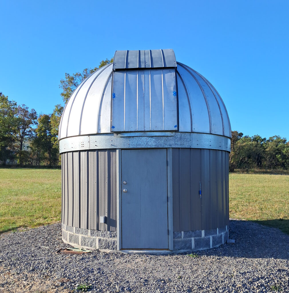
It’s now the end of September 2025 and with the help of my friend, the shutter has been reassembled and installed onto its tracks. This is another one of those moments I’ve been looking forward to for the longest time. From digging the pier hole until now has been a little over two years of work, and except for a few details the dome itself is done.
But there are still a lot of other tasks to complete before the observatory is fully automated and operational. The next important one to tackle is motorizing the shutter. The motor drive installation will be on the Dome Automation page.
I also need to turn my attention to weather and dust seals, since the dome did not come with any seals at all. It needs seals between the azimuth wheel ring and dome base, around the shutter opening, and on the rear of the shutter itself. I’ll also have to keep and eye on it through a few rain storms to make sure I’ve not missed any leaks before installing any astro gear inside.
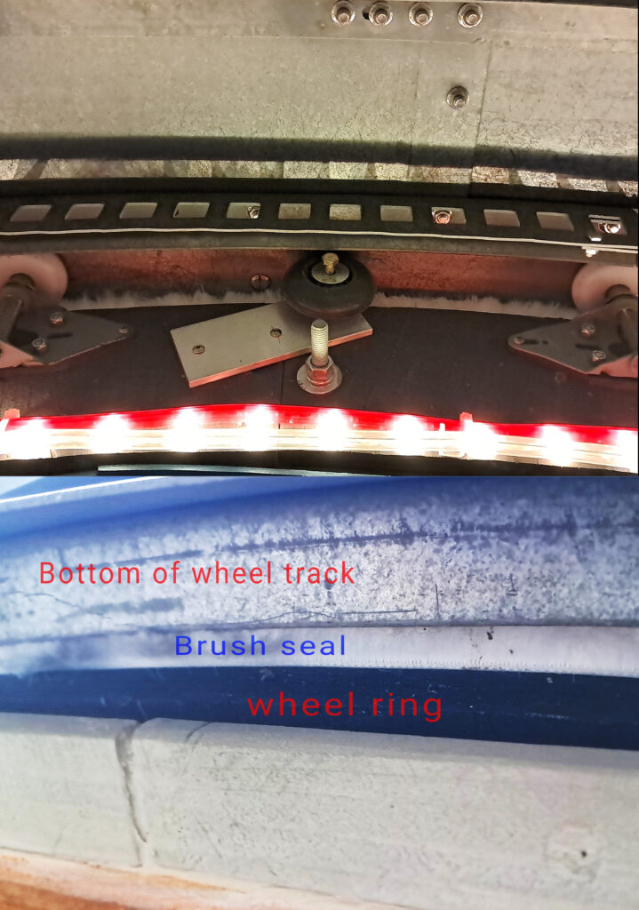
A brush seal was installed on the edge of the wheel ring, and sits flush to the bottom of the azimuth wheel track. The top half of the photo shows the seal from inside the dome, and the lower part shows the seal from underneath outside. It seems to work well enough, and should keep bugs and dust out, but only time will tell if the adhesive on the seal holds up.
After adding up all the expenses over the last ten years that I can remember for this project, including the initial cost of the dome, materials I didn’t already have on hand like framing lumber, plywood, cement and some blocks for the building, the backhoe for trenching, the costs of having missing dome pieces remade, and buying new stainless hardware and the steel pier, I have approximately $6,500 invested, plus two years of my labor.
Last Edited 11/09/2025