
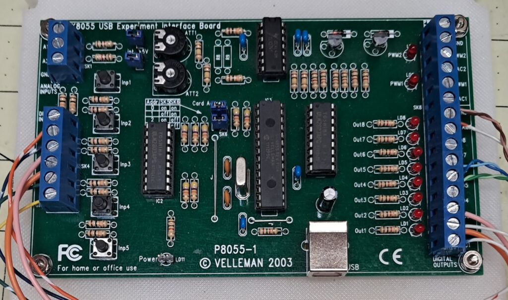
The USB controller used in my previous Exploradome observatory was the venerable Velleman K8055, and was controlled through Lesvedome software. I would like to continue to use it as the controller for my new dome’s drive, but I’ll need to come up with a new software driver for it.
Back when I used my Exploradome, all my computers ran Windows XP, 7 or 10 later on. On the job I was a Microsoft Certified System Engineer, as well as a Microsoft Certified Trainer, so I was very familiar with Windows. However, when Windows 11 came along and tried to force me to buy all new “Microsoft-approved” hardware, I drew a line in the sand. Now all my “old” laptops and workstations run on Linux, Linux Mint specifically, and I love it. I’m never going back.

All the motor controller electronics are built into a watertight housing, except for two relays that control the shutter motor and lower door actuators, which need to be mounted up in the rotating dome. There is a set of contacts at the park position to transfer power from the lower controller to the upper, plus two magnetic links to pass shutter/door open and closed feedback signals back down to the USB controller card.
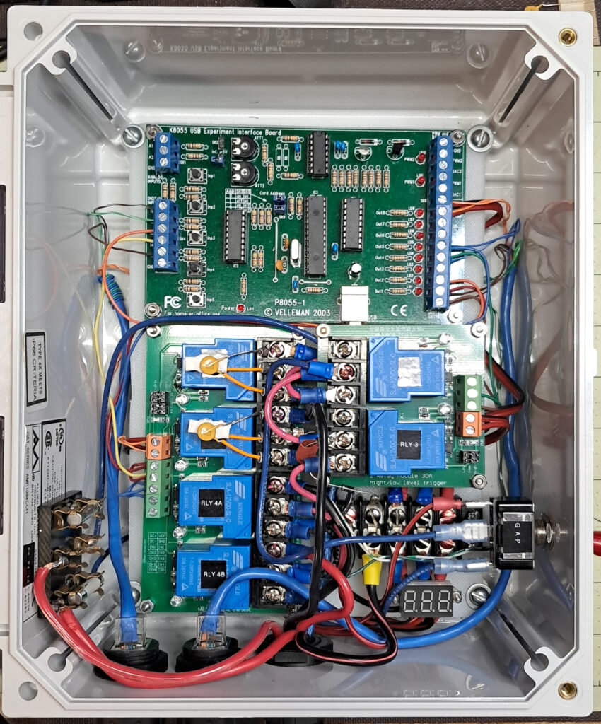
To fit everything within the box, and still have access to the USB socket on the bottom edge of the Velleman card, the double relay module is mounted on standoffs so the USB cable can route under it and plug into the USB socket. My old Exploradome controller was built as a prototype, so this time around I improved and simplified the design by using modern relay modules that are readily available online. It was necessary to update my original Lesvedome schematic somewhat to adapt it to the modules, but the end result is the same, and much neater than my prototype ever was.
One issue when using these relay modules is it appears no one makes a 30-Amp double pole double throw (DPDT) relay module. Instead, I used two single pole double throw (SPDT) modules with their input signal lines paralleled to emulate a DPDT relay. The six relays shown in the photo are set up to provide two SPDT and two DPDT relays.
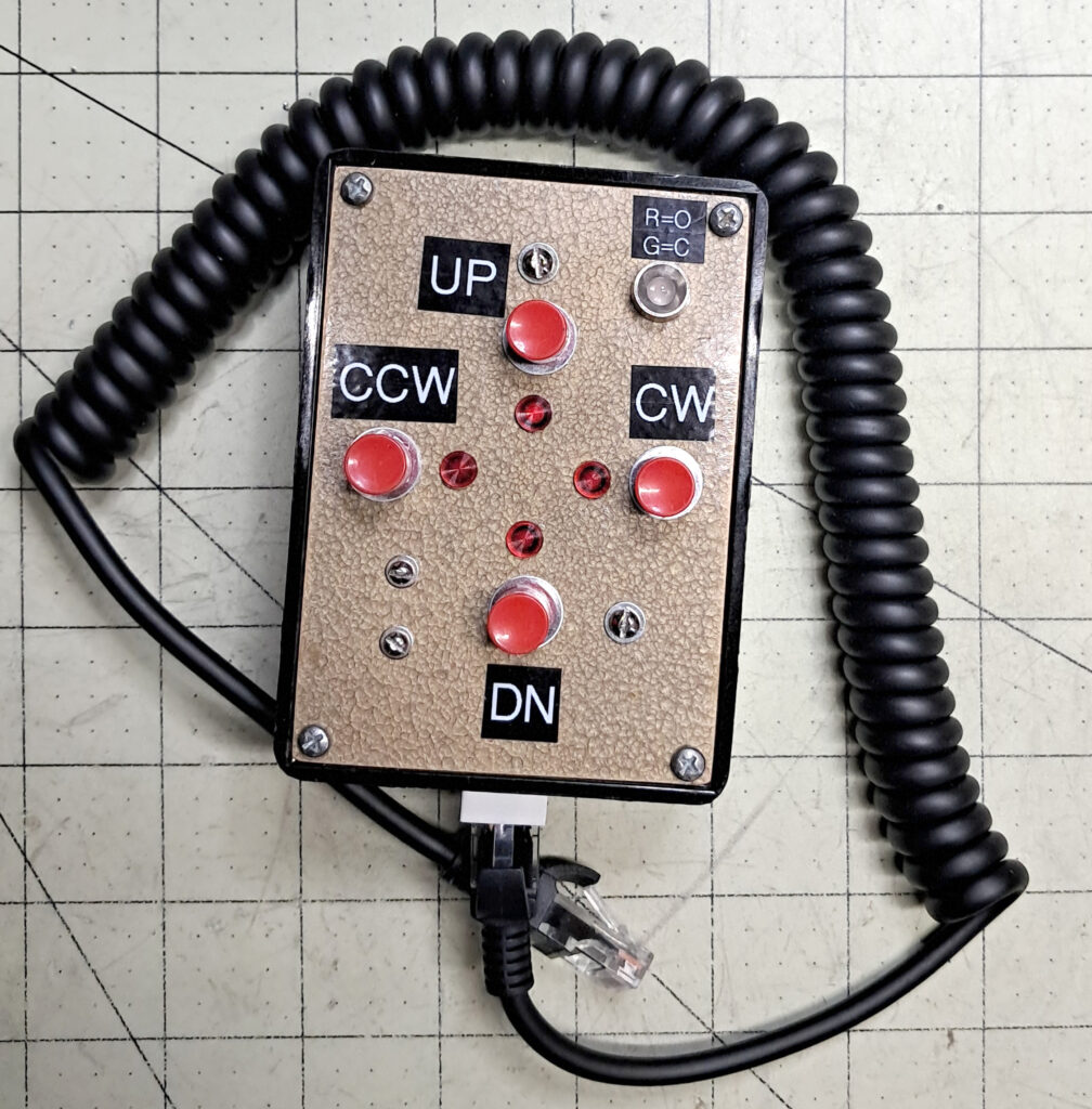
A hand controller is included for easy manual control. There are four control switches, two for the dome’s azimuth motor, and two for opening and closing the shutter/lower door. The four red LEDs next to the switches provide visual feedback, even when the dome is under software control. The handset interfaces to the main controller through an RJ-45 feed-through jack. Because some of the logic diodes are located inside the hand controller, it is an integral part of the main controller, and must remain plugged in during normal operation.
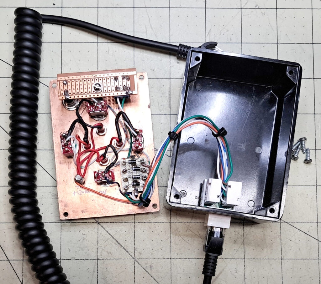
Inside the hand controller the circuit is fairly simple. Besides the four control switches and associated LEDs, there is another front panel mounted bi-color red/green LED on a small PCB. This LED indicates whether the dome is in an open or close cycle – red for open and green for close. There are also four logic diodes going to the switches, mounted on another small terminal board.
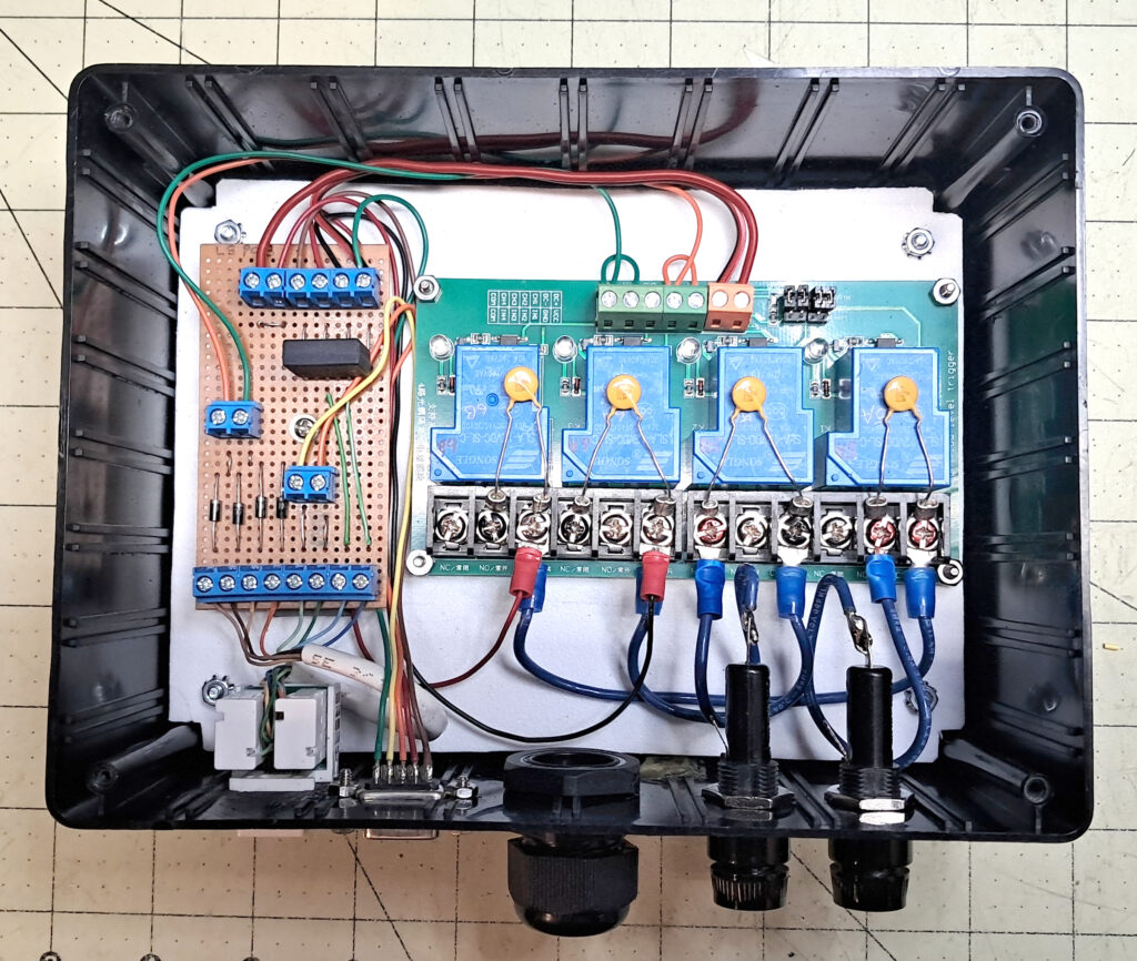
The upper dome control box contains only two DPDT relays, plus the components for the diode logic, and for providing +12VDC to power the four-relay module. As with the main controller, I used two pairs of SPDT relays, with their control signals paralleled, to emulate the DPDT relays.
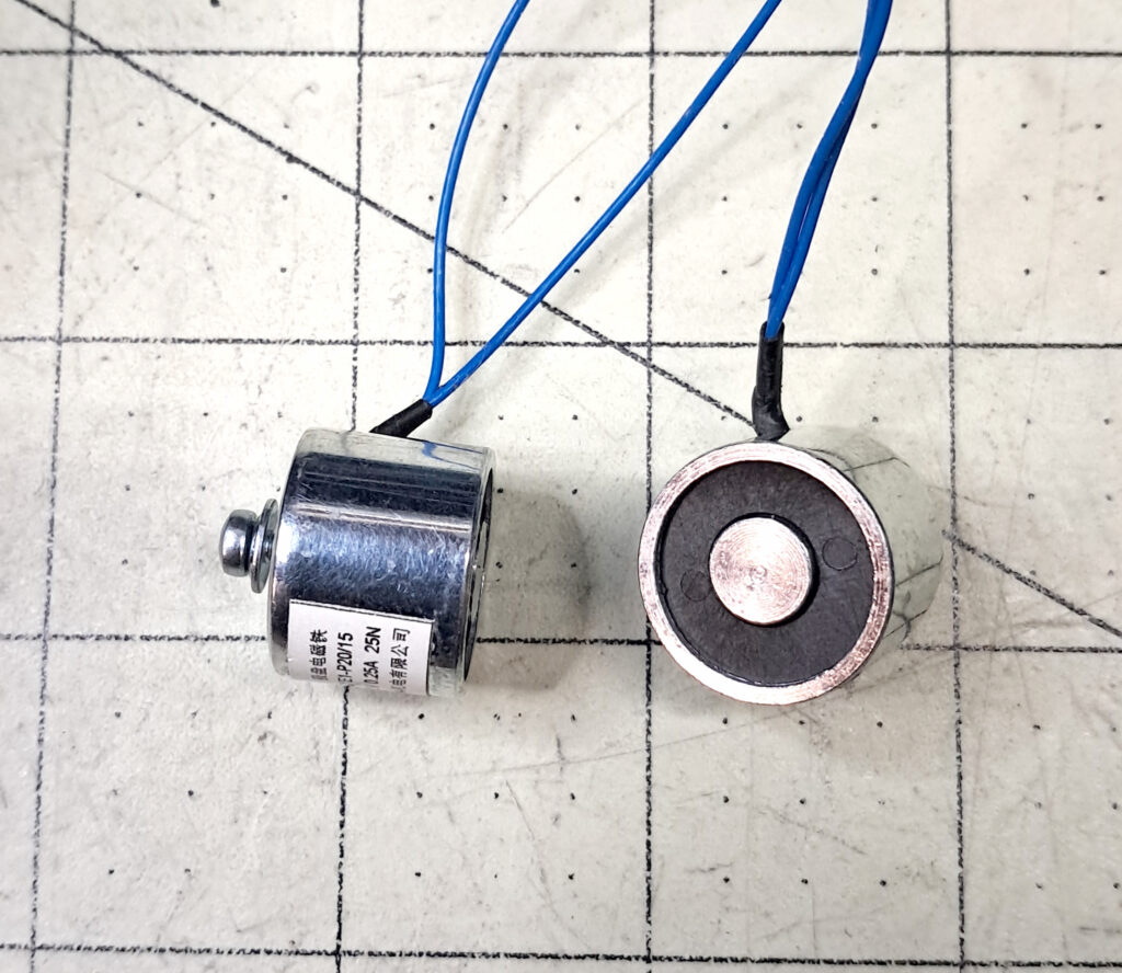
I added two control signals that were not on the original Lesvedome schematic. One signal indicates the completion of the Open shutter cycle, while the other indicates the end of the Close cycle. These two signals are coming from limit switches, so they are physically generated by movement of the shutter and lower door. They are not just a software timeout function as in Lesvedome, although adding a timeout as another layer of protection is a good idea.
The open/close cycles only run while at the Dome’s Park position, and each of the two feedback signals activates a corresponding fixed electromagnet in the upper dome that lines up over a matching hall sensor connected to the main controller in the lower dome when the dome is parked.
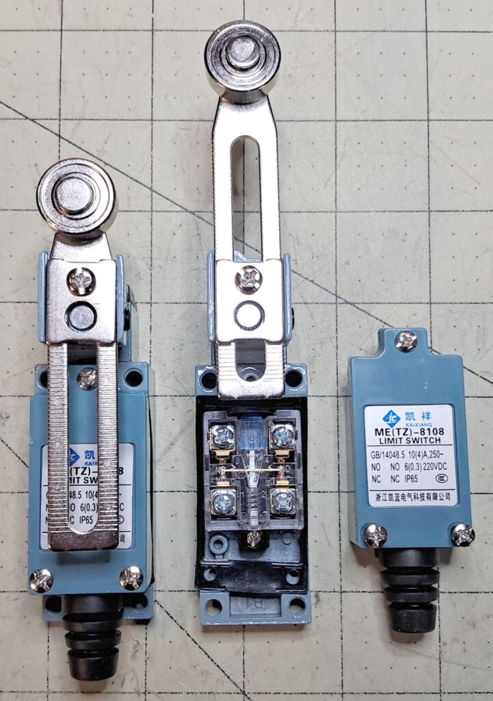
The limit switches are part number ME(TZ)-8108, and are, like most things these days, made in China. I found listings online for three versions. The cheapest one listed has a plastic roller and iron/copper contacts. The second has a metal roller and iron/silver contacts. And the third, which is the most expensive, is listed as having a metal roller plus copper/silver contacts. All the listings I found for this third version were out of stock, so I went with the second tier, which was a buck or so more than the cheapest option. It’s easy to tell the difference in the rollers, but I’m not sure how to tell if the difference in contacts are really as stated.
Each switch has one set of normally open (NO) contacts and one set of normally closed (NC), with no common between them. To make an SPDT switch, which is what I need, a jumper is added from one NC contact to one NO contact. This jumper obviously becomes the common.
I’m also addressing safety concerns as I go. For example, if a limit switch were to fail, there is a real possibility of damaging the dome or even injuring someone because the motors provide a good bit of torque, so I’m also incorporating additional emergency shutoff switches into the shutter controller. These will be an independent set of switches top and bottom for both shutter and door, positioned to cut power to the motors in case of a limit switch failing and the motor trying to drive the shutter or door into a hard stop. These switches will tie into the +12VDC power line to the associated relay module, cutting the power to the module if activated. All-in-all the controller will use a total of eight limit switches.
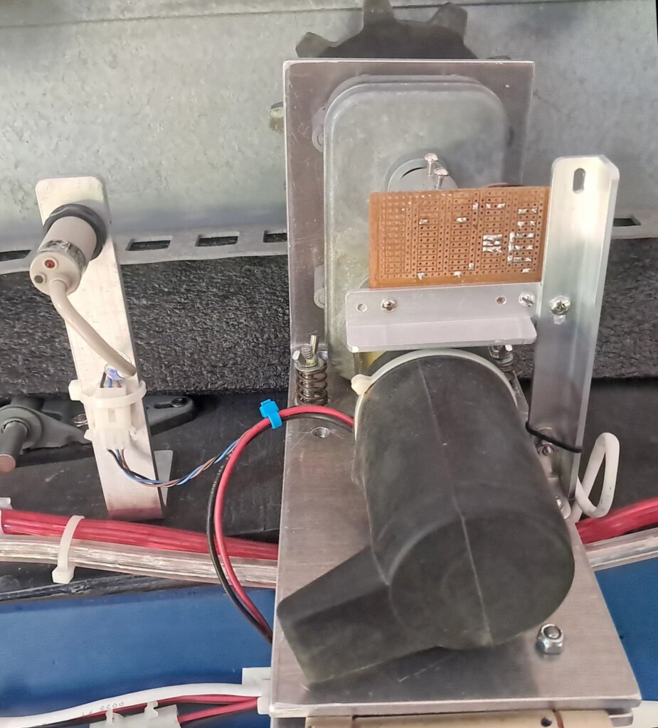
To complete the azimuth drive I need a gray coder for tracking the dome position. I was originally going to reuse parts from my old, Exploradome’s homemade gray coder, but then I found a Bournes contact encoder online, and it is smaller and not susceptible to stray light like my open encoder, so I’ll see if it works at least as well as the old design.
The old encoder disc I made has 24 holes, and this Bournes encoder provides 24 pulses-per-revolution. I expect it to work just fine, but I can’t fully test it until the dome wiring is finished and I can power up the main controller.
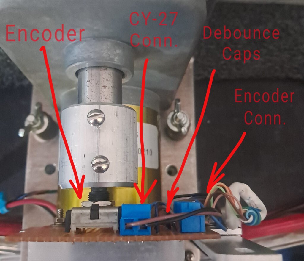
A closeup of the new encoder including a simple 3/4″ to 1/4″ shaft coupler made from a piece of leftover stock for the shutter rail spacers. The encoder board holds the Bournes encoder plus two 10nF capacitors to negate switch bounce noise. The digital inputs of the K8055 already have 5VDC pullup resistors, so none are needed on the board, and it all connects to the controller through the labeled encoder connector. The CY-27 home detector is also wired through the encoder board. This Bourns encoder part number is: ECW1J-B24-BC0024.
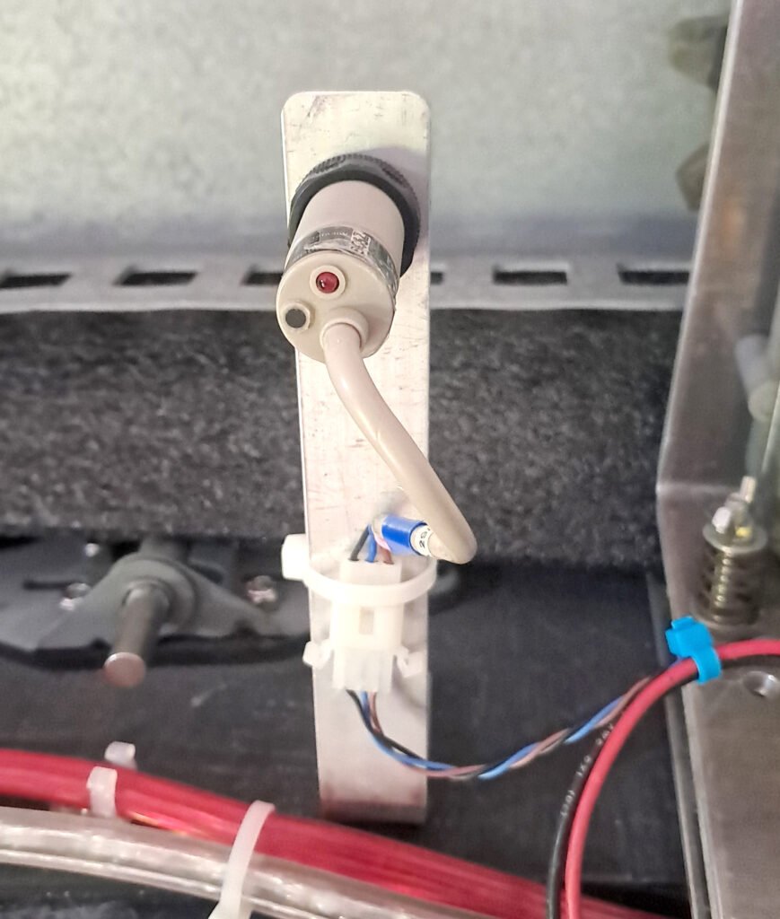
The home position sensor is an infrared photoelectric retroreflective device from SunX, model number CY-27. I bought it and a spare in a box of parts at a hamfest for a few bucks. It operates directly from +12VDC so no power conversion is needed. The reflective strip has not yet been installed on the dome wall. It connects to the encoder PCB where it picks up power and ground, and routes the output signal back to the controller through the encoder connector.
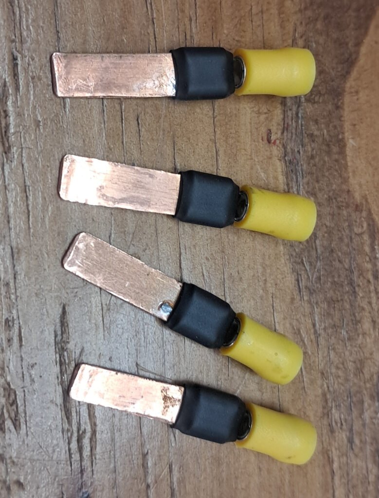
The 12VDC power supply for the dome is a model ESP115 from an old HP Compaq server. It can provide a max of 30-amps which is more then sufficient for the observatory. There is also a spare unit on-hand for redundancy. The only “issue” with this style supply is the output connector. The power supply original slid into a mating connector on a backplane, but I don’t have this backplane connector and couldn’t find anything comparable online, so I made a set of four blade contacts that will plug into it. They were constructed using push-on crimp terminals soldered to copper blades cut from sheet copper. Then the exposed portion of the terminals was insulated with hesatshrink.
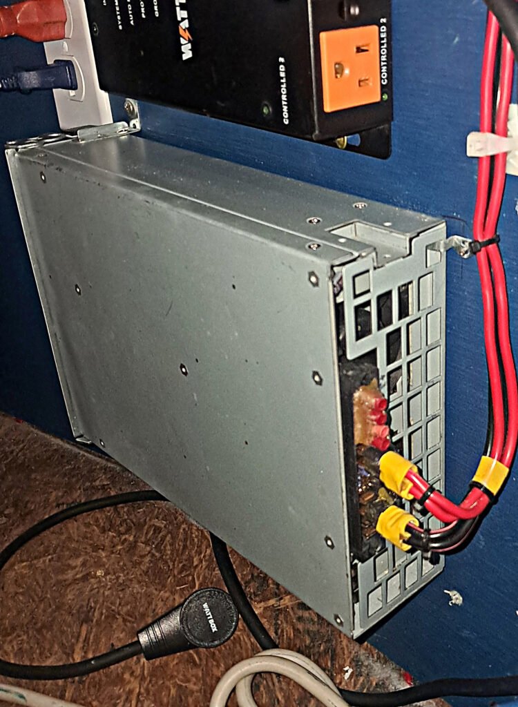
The back of the supply showing the completed wiring for +12VDC and GND using the blade contacts shown in the previous image. There are two blades/wires each for +12-volts and ground, which have been hot glued together for rigidity. The power supply also has 5VDC and 3.3VDC outputs which are not used and are covered with insulated terminals hot glued in place. I used hot glue because it grips well, but is easy to remove using IPA.
Power Transfer Contactor
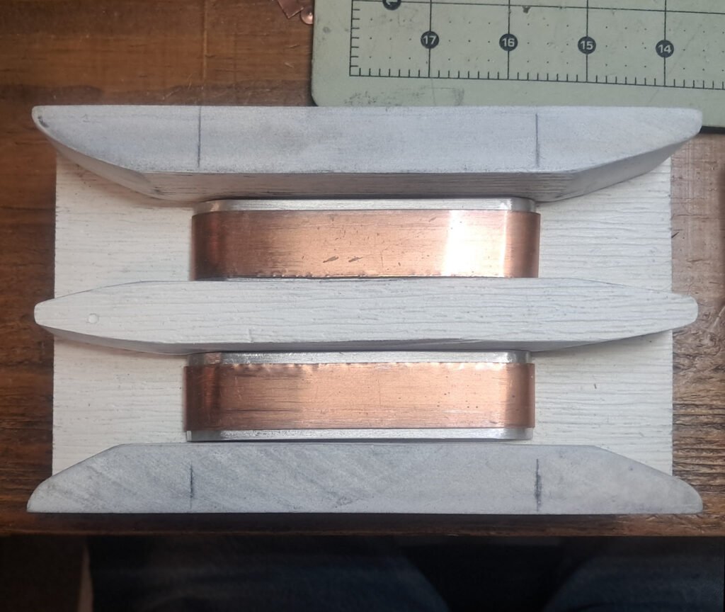
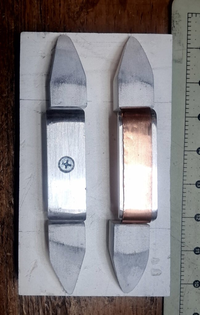
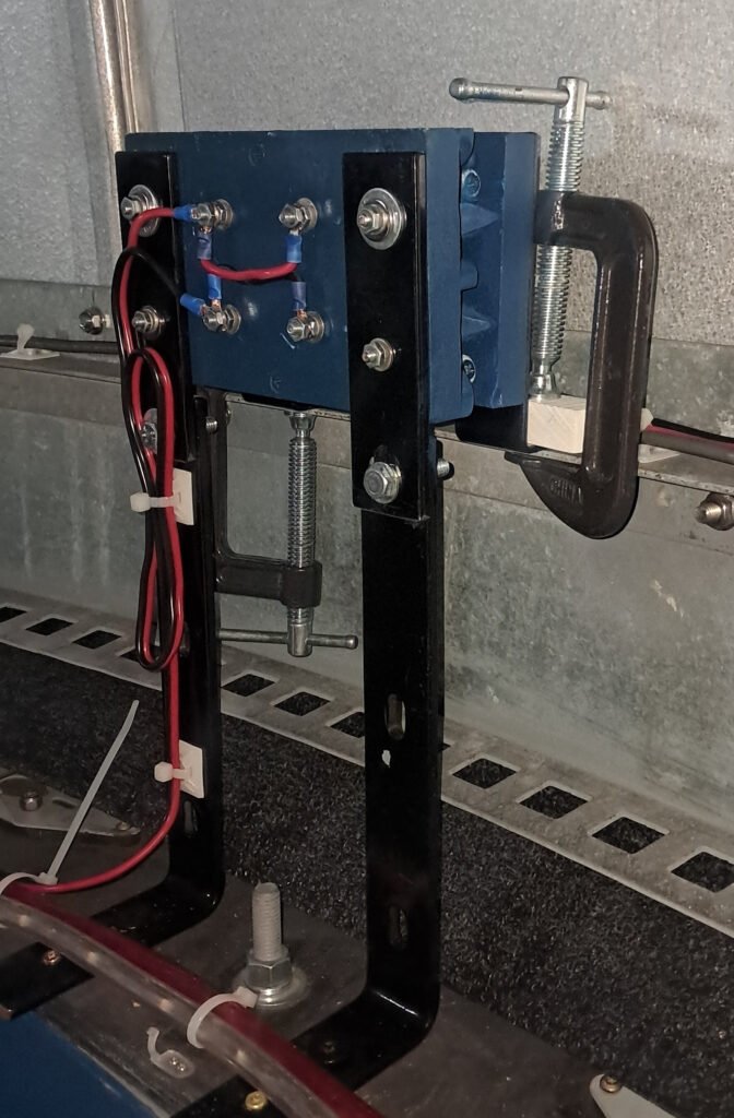
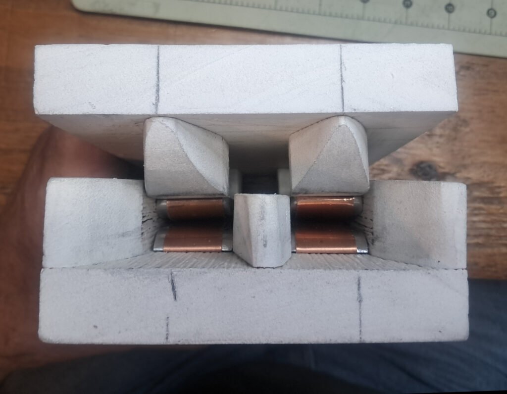
The contactor for transferring 12VDC from the lower dome to the rotating upper dome is constructed of pieces cut from a PVC decking board, and aluminium bar contacts covered with strips cut from a copper sheet. It’s a cross between the smaller contactor from my Exploradome and a design I saw online at Stargazers Lounge. The set of contacts that rotates with the dome are spring loaded to apply pressure when the contacts are closed. The aluminum bars are cut from 1″ wide by 1/4″ thick bar stock. The copper sheet was purchased at a hobby shop. The aluminum made good contact, but there was more friction as the pieces slid over one another than with the copper. The copper slides very smoothly and, of course, conducts even better than aluminum. It is working well and I have manually powered the shutter motor through it with no problems, but I still need to do some final testing once the limit switch wiring is finished. It’s rotating half is just clamped in place at the moment for testing and will be drilled and bolted down once that’s done. And as shown, I painted it the same star chart blue as the walls.
Using a contactor like this means the shutter only opens or closes in the park position. I never found this to be a problem with the Exploradome, so I’m using the same approach with this dome. There’s really nothing needing power in the upper dome during observing or imaging sessions.
Upper Controller Installation
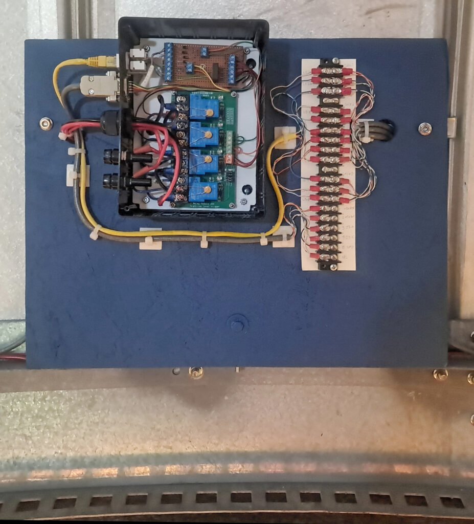
The upper controller (minus cover) mounted in the dome. A piece of painted plywood was installed for mounting the control box and an interconnecting terminal strip for cross-connecting limit switches into the controller. I was originally planning to run all wiring through connectors directly into the controller, but this would have required a much more complex wiring harness. The terminal strip makes troubleshooting and wiring changes much easier. The exposed connections will will get a clear acrylic cover plate once the wiring is finalized.
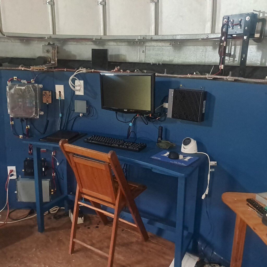
The overall setup of the PC and controller as currently configured. The upper controller is just out of view to the right of the contactor.
Work still awaiting completion includes installing the hard stops in the shutter tracks, installing the limit switches, and installing the drop-down door actuator(s). All of this is currently in the works.
I also need to install the weather stripping around the shutter, and the rear shutter cover for keeping rain from blowing in the back, as soon as I’ve get the shutter operating safely.
Page last updated 09/04/2026