
Since this new 12-1/2′ metal dome is several times heavier than my old Exploradome, it needs a more robust drive system. This new drive uses heavier, more powerful DC gear motors and linear actuators as a result.
Azimuth Drive
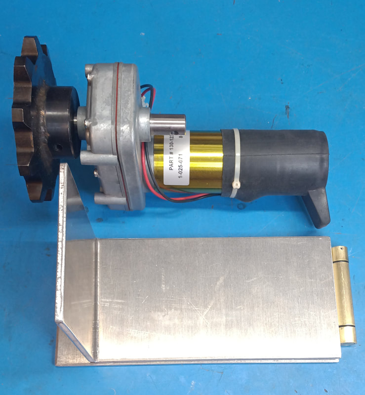
The motors for both the Azimuth and Shutter drives are 12VDC gear motors originally designed for extending RV camper slide-outs. According to the manufacturer’s spec sheet online, in normal operation the motor is meant to provide about 400 in-lbs of torque at around 9.5-amps, and at no load the speed is around 12RPM. It also has an integrated brake with a holding torque of 500 in-lbs. The gearbox attached has a ratio 163:1. I purchased the sprocket separately.
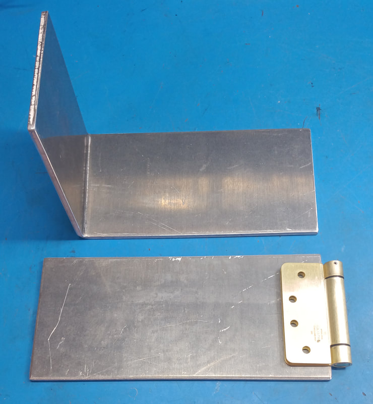
The metal components for a simple motor mount were made by a local metal fabrication shop that builds semi and dump truck beds. This is the same 3/8″ material they use in the truck beds.The shop cut and bent the pieces, but I did the drilling and assembling of the plates, hinge and motor. This mount is more or less of the same design that Ash shows in their dome construction manual that I have. But this one is built specifically for this gear motor.
The hinge shown is a commercial-grade door hinge, which is higher quality than typical cheap door hinges. I learned from my ExploraDome drive not to use a really cheap hinge, because it rattled incessantly whenever the dome was in motion. Unfortunately, the only version of this hinge I could find locally is spring loaded to automatically close the hinge (and door) which is opposite of what I need. The spring-loaded hinge pin is not solid, which causes a bit of side-to-side flop, so I disassembled it and replaced the two-piece pin with a solid steel one.
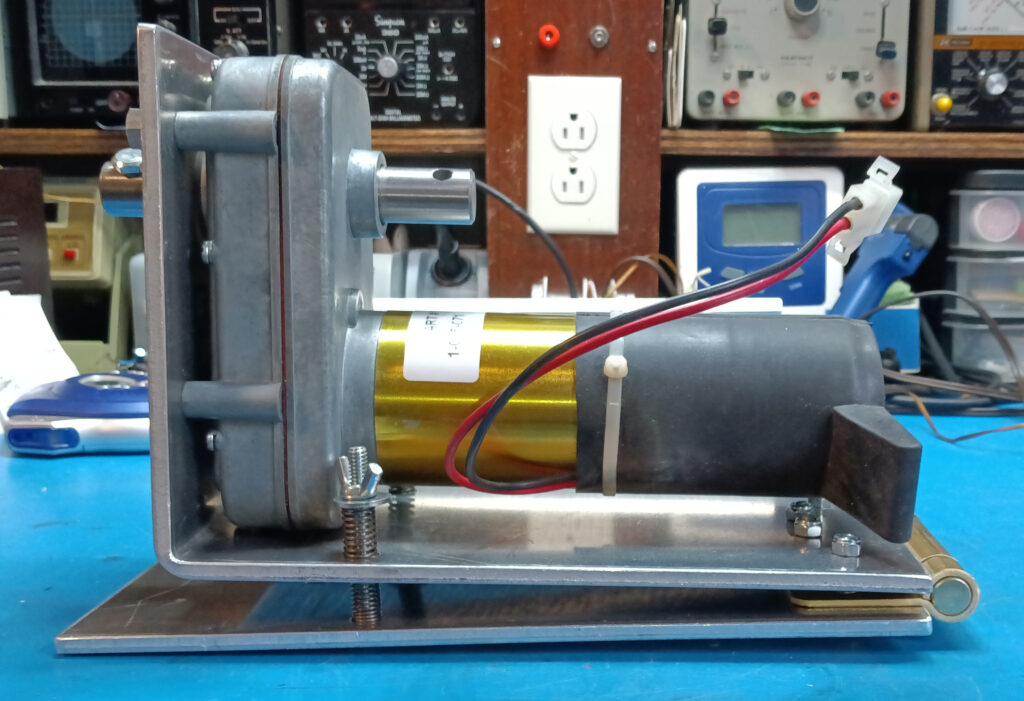
In this photo, drilling and assembling the mount is done, and the motor is bolted up. The two hinged plates are spring loaded to control how much the sprocket engages with the drive track. All that’s left to do is bolt the mount onto the dome ring and install the drive sprocket. Once it’s working manually, I’ll make a gray coder to integrate it with the motor drive circuitry.
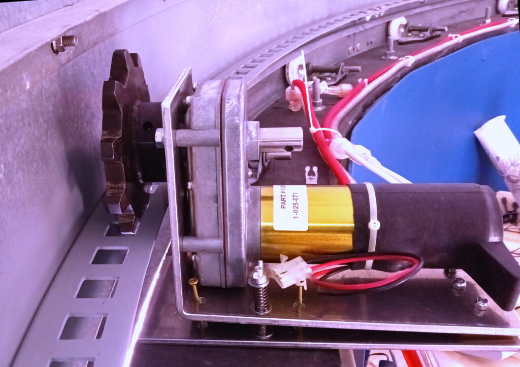
The azimuth motor drive is now installed. In testing, a 12-Volt 8-Amp gel cell battery ran the drive easily; drawing only about 5-amps. One full rotation takes 3-1/4 minutes (the circumference is 39-ft 3-in).
In the Ash manual, they use a right-angle gearbox on the azimuth drive, so that their big AC motor sits parallel with the dome. But because my DC motor already has a 163:1 gearbox directly attached, and is much smaller, it can sit perpendicular to the track and directly drive the dome without protruding enough to be a hazard.
Shutter Drive
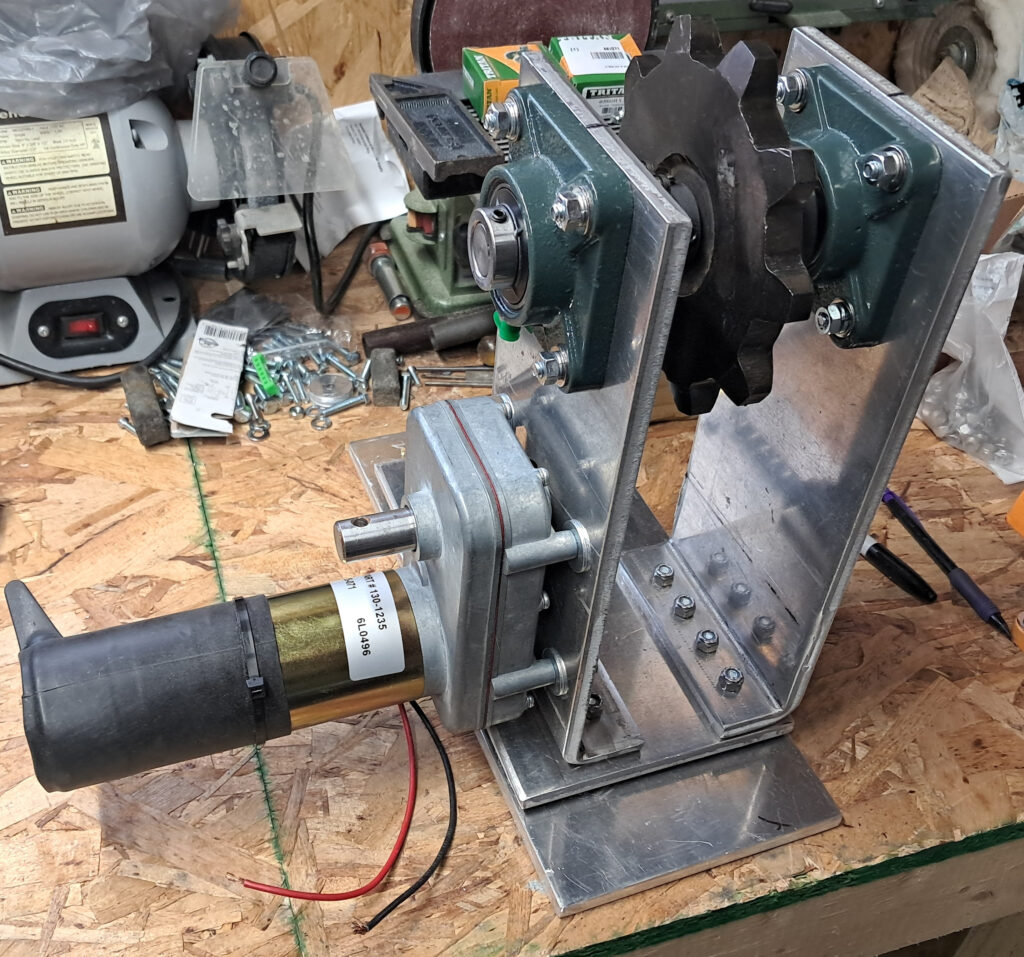
While the Azimuth drive was relatively simple to construct, the shutter drive was a bit more of a challenge. I hadn’t really wrapped my head around what this drive was going to look like until I got to the point of sliding the shutter frame in place on top of the dome. Then I could see that the motor and sprocket were not going to engage into the track, with the gear mounted directly on the motor shaft. And I couldn’t just use a larger sprocket because it would require too large a hole in the top of the dome. So I ended up building a mount similar to what is I saw in the Ash manual.
The completed mount has a separate shaft at the top for the drive sprocket, and is driven by a chain drive to the motor mounted below. In the Ash manual it looks like they used some type of gearbox, but gearboxes can get expensive and heavy, so I went with the chain drive as a simpler, cheaper option. And it reduces the total weight that has to be suspended from the dome.
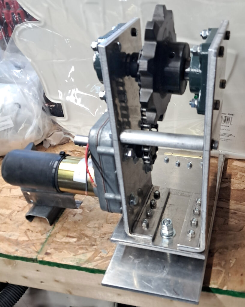
The drive assembly is made from 3/8″ thick aluminum plate that was cut and bent at the same fabrication shop as the azimuth mount. Again, I measured, drilled and assembled the drive myself. The upper keyed shaft is 3/4″ in diameter, and rotates in bearing blocks. The chain drive between the sprocket and motor is made with #41 chain and 10-tooth sprockets.
The hinged mounting plates were originally spring loaded to keep the sprocket pushing up on the track, but after more testing I decided the mount works better just blocked solidly in place. There wasn’t enough upward play between the sprocket and track to worry about, (the 2″ wheel tracks limit movement) and the sprocket stays securely seated in the drive track throughout the full motion of the shutter, so it turned out that no spring was actually needed. The hinged upper plate now just adjusts the angle at which the sprocket engages with the track.
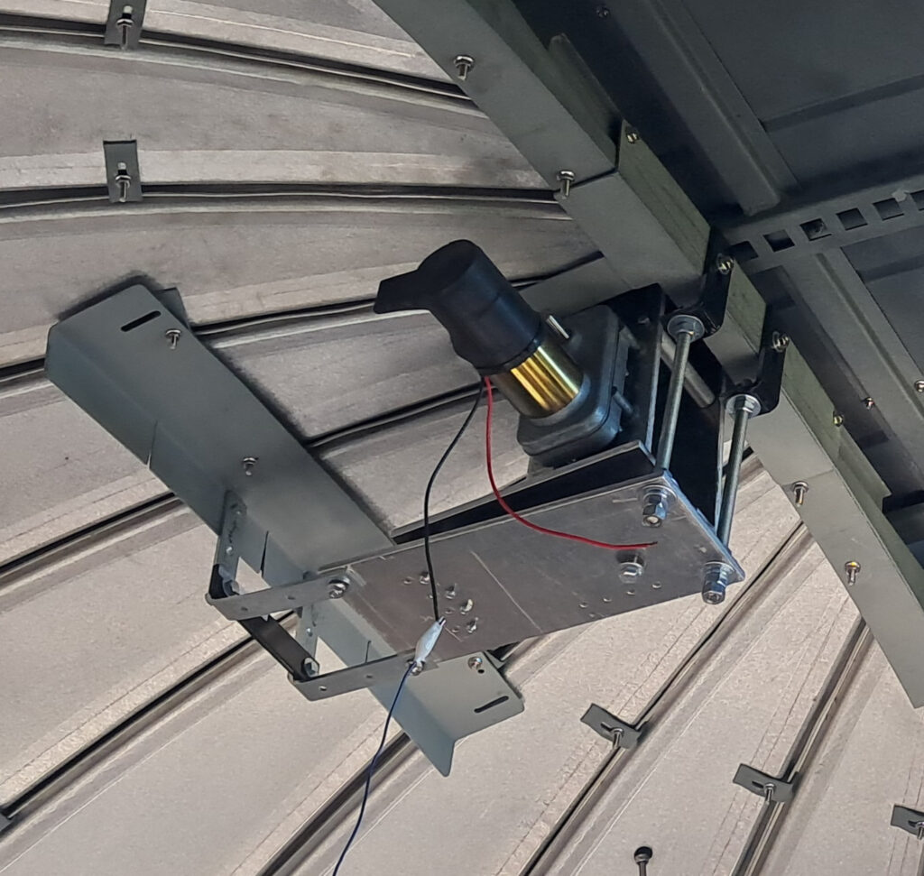
It took a while to work out how to mount the shutter drive up in the dome, but it’s safely up there. In front it is attached using 1/2″ threaded rods through angle iron mounting points. The angle iron hangers are bolted to the reinforced cross-member at the top-back of the shutter opening. The threaded rods allow adjustment of motor height and engagement of the drive gear into the track.
In the rear a 24″ long right-angle bracket is mounted across the dome panels to create attachment points for two 1/4″ thick angled metal brackets that secures the rear of the bottom plate to the dome.
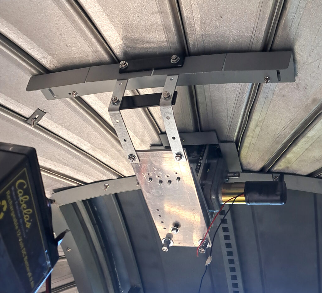
A look from behind at the motor drive and rear brackets. Now I need to run the power cable up to the motor so I can stop climbing a 10-foot ladder with a battery.
Lower Door Linear Actuators
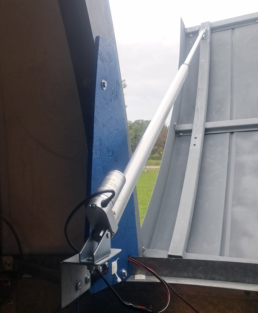
I’ve also been working on installing linear actuators to open and close the lower shutter door. The first actuators I tested had approximately a 30-inch extension, which was longer then actually needed, but they did work, with a couple of caveats. One actuator was mounted on each side of the door, but the speed of the pair was not well matched, which caused binding as the door opened. They have 12VDC motors so I could have added a resistor to the faster actuator to slow it down, but there is another issue. The actuators don’t have built-in limit switches and that creates a problem that is not easily solved.
While I can try to match the speeds, I will never get them exactly the same, there are just too many variables involved. If these actuators had limit switches, the drive speed error between them would get zeroed out every time they extended or retracted and hit the switches. But without that any motion error accumulates over time and the door binds again. The simplest and safest solution is to just replace both actuators with ones containing switches. The new style shown in the photo have limit switches and are also the correct length (the length must be correct for the limit switches to work).
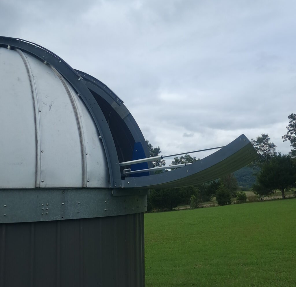
A view of the open door with both of the new actuators installed. Their load capacity is 2000N each and the speed of the drive motors is more closely matched than were the old ones. By design, the door will not be exactly horizontal when open. It’s not necessary as the horizon is obstructed by trees and the seeing is poor on the horizon anyway, but the main reason is leaving the end of the door a bit elevated presents less of a hazard to people, especially as the open door rotates.
At this point all three mechanical drive systems are working. I now need to finish integrating the drive electronics.
Page last updated 10/02/2026